


 Magnetic Card Reader
Tel: +86-769-8118 3549
Fax: +86-769-8255 1233
E-mail: info@lintechtt.com
Add: 3/F, Blcok A8, Kaida Creative Industry Park, Qiaochang Road, Qiaotou Town, Dongguan City, Guangdong,China.
Skype: lintechco
Skype: lintech03
Skype: lintech04


Magnetic card card reader sensitive design factors.
--For experience and reference in magnetic card reader design.
Technical information stored by the magnetic pattern first appeared in the audio recording field. Since then, the concept has been extended to apply to many types of products, such as floppy disks, audio / video tapes, hard disks and magnetic stripe cards. This article will focus on the widely used in global financial transactions and access control in the magnetic stripe card.
Reading the magnetic stripe cards in addition to the decoded data outside the digital logic also requires a very important analog circuits. Data is recorded on a magnetic digital process by completing the magnetic stripe along the length of the magnetic particles. The card has successfully read quite a challenge, since the amplitude of the sensor signal will draw cards with the speed, quality, and magnetic card reader heads sensitivity varies in practical applications. Moreover, the frequency will be with the draw card speed changes. This requires that the analog circuit can adapt to these changes, without distortion sensor signal processing. This article describes how to handle mechanism sensor signal changes.
Magnetism and Magnetic
In order to understand the impact of swipe-card speed, quality, and magnetic sensor sensitivity, understanding how information is stored on the card and it is important how the reader head is detected. In the magnetic storage system, the information is represented by a polar pattern such as iron oxide magnetic material. Figure 1 shows the magnetic stripe on the magnetic coating material. Particulate magnetic materials may be arranged in a particular direction, or because not previously been irradiated in a specific direction of the magnetic field in a random direction. However, if the external magnetic field is applied to certain particles on the magnetic strip will be arranged in accordance with the direction of the external magnetic field.
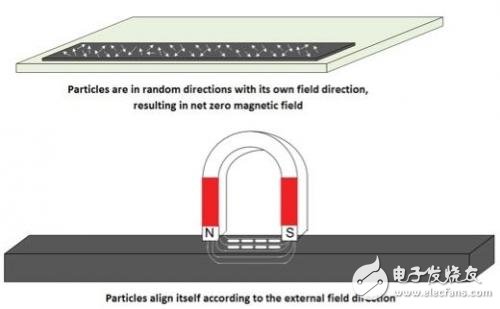
Figure 1: magnetic material arranged under the influence of an external magnetic field in a specific direction
In practical systems need to use a write head, it is actually around the core of a coil. By controlling the direction of the coil current magnetic field can be easily programmed. This helps the formation of polar pattern on the card. The narrower the gap between the magnetic poles, the magnetic card can be programmed data density is higher.
In the F2F coding scheme, if the pole shift occurs in the bit period, it represents a logical 1, otherwise it represents a logical 0. For example shown in Figure 3, if the bit period is Δ, and the pole shift occurs at Δ / 2 place, then this bit is a logical 1, otherwise logic 0. Note that the length logic 1 and a logic 0 on the card occupies the same. However, the bit period Δ will vary with the draw rate card, this issue must be addressed in the reader.

Figure 2: Power magnet magnetic stripe means logic 1 and logic 0, which uses the F2F coding scheme

Figure 3: pole pattern and data
It is worth noting that the length of the bit period a logic 1 and a logic 0 is the same.
Depending on how much information, the data to be encoded on a separate line, the line is called a track. You can have a maximum of three tracks on the magnetic card.

Figure 4: Track on the card
Reading the process is reversed, it requires the use of a coil structure shown in Figure 2 - the same core reader head. It notes that each have a sensor track. When draw cards from magnetic stripe reader head magnetic field in the coil induces a voltage. Figure 5 shows the waveforms obtained from the first reader.
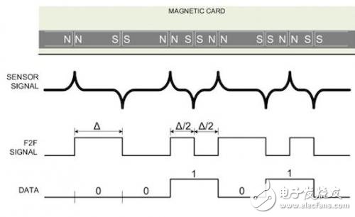
Figure 5: The first reader (sensors) Signal
Peak signal appears at each flux conversion. This is because at the edge of the pole with a high density magnetic flux. As you can see, the information is represented by the position signal peaks. Peak detector circuit can decode this signal, or very close to the threshold of the hysteresis comparator signal peaks. But before we give this signal detector circuit, also requires additional processing, the following reasons:
Swipe-card speed: speed scratch card unit specified as inches / second (IPS). Generally, the requirements for magnetic card reader can work within the Cards in the speed range of 5 IPS to 50 IPS. The amplitude of the sensor signal with the draw card speed changes. Card draw speed increases, the rate of change of magnetic flux in a coil reader head cut also increases, so that the signal amplitude becomes large. In contrast, when the draw card is slow, the signal amplitude will be reduced, thereby increasing the difficulty of reading the data.
Magnetic Quality: With the increase of the amount of use and the passage of time, the quality of the card with the magnetic field strength and reduce the distortion due to the dust and scratches on the card caused by increased and decreased. These factors combined to reduce the amplitude of the sensor signal.
Reader head sensitivity: the first reader sensitivity depends on the number of turns and the spacing between the magnetic stripe reader head.
Due to the influence of all these parameters, the signal amplitude may vary between a few hundred to tens of uV mV. This range can be compensated by an amplifier. But not with a fixed gain amplifier. When planning a high speed card, the card and very good quality, the amplifier output can be saturated to the supply rail voltage. When the signal is saturated, information in the time between two consecutive peaks of the difference between the representative will be lost. So faithfully amplify the sensor signal does not cause saturation or waveform change is very important. This requires the use of an amplifier gain can be configured, so that we are ready to adjust the gain. To do this, the system must be able to detect weak signal timing. This can be used to track the sensor signal ADC to find approximate signal peak to achieve.
Figure 6 shows a complete system. Preferably made of two amplifying circuit with ADC receiving the first stage of the output circuit. This eliminates the need high-resolution ADC, 8-bit ADC is sufficient to meet the needs of this application. The first stage may be a fixed gain amplifier, a variable gain amplifier may be. The second stage is a variable gain amplifier. CPU reads the ADC result, and by adjusting the gain of the signal output of the second amplifier stage to achieve the best. Output of the second amplifier stage is supplied to the peak detector / hysteresis comparator circuit peak detection. The pulse output from the detector is fed to the timer time difference measurements, and then decoded by the CPU 1 and 0.

Figure 6: block diagram of a magnetic card reader
Thus if there still exists a problem of data loss before gain renewal. To avoid this problem, the card will use the two leading zeros encoded to synchronize (this can support bi-directional swipe the card). The aim is to enable the decoder to synchronize to swipe the card speed. For example, the track 1, a total of about 62 leading zeros. Track 1 has a data density of 210 bits. Therefore, we can estimate the leading zeros will continue to draw cards when speed is about 5 IPS 60ms time, swipe-card speed is 50 IPS leading zeros will continue 6ms. On the other two tracks, it is more or less the same, as 7. When human Cards in the beginning of 50 IPS draw card speed it is impossible, so the system has a much longer time than 6ms to measure and adjust the gain peak. Figure 8 shows the gain control process.

Figure 7: three track magnetic card contents
Note that, CPU card during the draw is likely to continue to fine-tune the gain to accommodate changes in amplitude. Under normal circumstances, along the direction of the draw card, scratch card speed will increase, thereby increasing the signal amplitude. Note that when using a constant speed automatic draw card swipe-card machine that this view is not correct.

Figure 8: Gain change process
Achieve magnetic card reader
Figure 9 shows the Cypress PSoC-based dual-track magnetic card reader 1 implementation. PSoC 1 processor with integrated 8-bit processor core with configurable analog and digital blocks on a single chip integrates all the functions. It should be noted that the passive devices shown in the figure is the external processor.

Figure 9: PSoC 1 card reader
Because the sensor signal may be negative, and therefore must be offset DC. In PSoC, the analog signal 1 may be different from the power supply to ground reference. This referred to as analog ground (AGND), the input signal is clamped to the analog ground. Followed by signal amplification with two programmable gain amplifier (PGA). PGA is a continuous time analog module implementation. It has a resistor array, when configured for changing the gain of the amplifier. The gain can be configured as one of 18 options between 1-48. CY8C28243 PSoC 1 integrates a maximum sampling rate of 150ksps 10-bit SAR ADC.
CPU reads the ADC, and then control the amplifier gain. The amplified signal is supplied to the hysteresis comparator generates a digital signal peaks close to the edge signal. CPU must then adjust the gain of the amplifier, so that the threshold value close to the peak, but not exceed the peak. This helps to avoid timing error when the card jitter occurs. Hysteresis comparator output is supplied to the timer pulse width measurement. CPU reads the timer output, and decode data logic 1 or 0. When the draw card, CPU packed data bits, check for errors, and then through I2C, SPI or UART interface data to the host.

